NAME
RPi::WiringPi::FAQ - FAQ and Tutorial for RPi::WiringPi
DESCRIPTION
This document will hopefully provide enough information in a sane way to get you well on your way with manipulating your Raspberry Pi with the RPi::WiringPi and related distributions.
In this document we use constants that are provided with the :all tag in RPi::Const module.
GLOSSARY OF TERMS
HIGH         -  Outputting 3.3v
LOW          -  Connected to 0v (ground)
floating     -  The state where a pin is not stable at HIGH or LOW
PWM          -  Pulse Width Modulation (potentiometer-like)
INPUT        -  Pin is listening only
OUTPUT       -  Pin is active in turning things on/off
PWM_OUT      -  Pin is OUTPUT, but PWM capable
GPIO_CLOCK   -  Pin is used for timing
PUD          -  Internal pull up/down resistor
PUD_UP       -  PUD resistor pulled to HIGH
PUD_DOWN     -  PUD resistor pulled to LOW
EDGE_FALLING -  Triggers when a pin goes from HIGH to LOW
EDGE_RISING  -  Triggers when a pin goes from LOW to HIGH
EDGE_BOTH    -  Triggers when either of the above two states
OLED         -  Organic Light Emitting Diode
DPOT         -  Digital potentiometer
ADC          -  Analog to digital converter (in)
DAC          -  Digital to analog converter (out)
IC           -  Integrated Circuit
GPS          -  Global Positioning System
TPV          -  Time-Position Velocity
RTC          -  Real-Time Clock (RTC)
SETUP
Perlbrew configuration
perlbrew lets you run this software under your own, up-to-date Perl instead of the system Perl, which keeps your project isolated from the OS toolchain. It is recommended, but not required - and in particular you do not need a threaded Perl. Interrupts run their listener in an internal C thread and dispatch your callbacks in your own interpreter (see "Interrupt usage"), and background work via $pi->worker is fork-based by default (see RPi::WiringPi::WORKERS, RPi::WiringPi and WiringPi::API). A threaded Perl is only needed if you opt in to worker(..., {mechanism => 'thread'}).
As your normal, every day user, install perlbrew:
\wget -O - https://install.perlbrew.pl | bash
echo "source /home/pi/perl5/perlbrew/etc/bashrc" >> ~/.bashrc
sudo reboot
First thing to do is to install the appropriate cpanm version:
perlbrew install-cpanmThen, install an instance of Perl, and switch to it:
perlbrew install perl-5.30.0
perlbrew switch perl-5.30.0
sudo configuration
Note: Only when using PWM features do you need to use sudo. All other aspects of this software work properly with a non-privileged user account.
To use sudo to run your scripts within the appropriate Perl installation, you need to modify the /etc/sudoers file. Prepend the string value for the secure_path directive to include the path to the new perlbrew managed perl, followed by a colon. For example: /home/pi/perl5/perlbrew/perls/perl-5.30.0/bin:. Leave the existing part of the string in place.
Test that it looks correctly:
sudo echo $PATH...your new path should be the first entry in the environment variable.
Now, you can do everything with the normal user account, using their personal installation of Perl, and you just need sudo to run your scripts, leaving your default system installation intact.
Note: Your user account must be a member of the gpio group for non-privileged access to the GPIO peripheral (through /dev/gpiomem). On current Raspberry Pi OS the default user is already in this group, but if you run as a different user you must add it yourself. This is also required on the Raspberry Pi 5, where cleanup restores certain pins to their default "no function" state by shelling out to pinctrl (which likewise needs gpio group membership). If you see "Permission Denied" errors accessing /dev/mem or /dev/gpiomem, add your user to the group and log back in:
sudo adduser pi gpioCrontab Configuration
If you plan on running RPi::WiringPi scripts from within crontab as your normal user account, you need to set a logind flag so that the shared memory semaphores don't get removed upon logout.
In /etc/systemd/logind.conf, change:
#RemoveIPC=yes...to:
RemoveIPC=noThat is, remove the comment hash, and change yes to no.
I2C configuration
You need to have some core software installed before using the I2C bus. The Raspberry Pi 3 already has everything pre-loaded. On a typical Unix computer, you'd do something along these lines:
sudo apt-get install libi2c-dev i2c-tools build-essentialTo test your I2C bus:
i2cdetect -y 1...or on some machines:
i2cdetect -y 0First thing you need to do is enable the I2C bus. You can do so in raspi-config, or ensure the dtparam=i2c_arm directive is set to on in the /boot/firmware/config.txt file (/boot/config.txt on releases before Bookworm):
dtparam=i2c_arm=onNote: If you get permission errors accessing the I2C bus, you may need to add your user (eg. pi) to the i2c group:
sudo adduser pi i2cNote: The test suite gates tests that require a live I2C bus behind the RPI_I2C environment variable. If the I2C bus is disabled (or you simply don't want to exercise it), leave RPI_I2C unset and those tests will be skipped rather than failing. To run them, enable the bus as above and set the variable before running the suite:
RPI_I2C=1Arduino I2C configuration
Often, the default speed of the I2C bus master is too fast for an Arduino. If you do not get any results, try changing the speed. On a Raspberry Pi, you do that by setting the dtparam=i2c_arm_baudrate directive in the /boot/firmware/config.txt file (/boot/config.txt on releases before Bookworm):
dtparam=i2c_arm_baudrate=10000SPI configuration
First thing you need to do is enable the SPI bus. You can do so in raspi-config, or ensure the dtparam=spi directive is set to on in the /boot/firmware/config.txt file (/boot/config.txt on releases before Bookworm):
dtparam=spi=onNOTE: If you get permission errors accessing the SPI bus, you may need to add the pi user to the spi group:
sudo adduser pi spiSerial configuration
To use GPIO pins 14 (TXD) and 15 (RXD) as a serial interface, the procedure differs by board. On all boards, first free the port from the kernel console: in raspi-config, under Interface Options -> Serial Port, answer no to the login shell and yes to the serial hardware.
Raspberry Pi 3 / 4 (and Zero W): the on-board Bluetooth modem is wired to the primary PL011 UART, leaving GPIO 14/15 on the inferior, baud-unstable mini-UART (/dev/ttyS0). To move the good UART onto the header pins you must disable Bluetooth. Edit /boot/firmware/config.txt (/boot/config.txt on releases before Bookworm) and add:
enable_uart=1
dtoverlay=disable-bt
With that overlay the header serial port becomes /dev/ttyAMA0.
Raspberry Pi 5: Bluetooth has its own dedicated UART and is not shared with the GPIO 14/15 pins, so there is nothing to disable. Just enable the header UART in /boot/firmware/config.txt:
enable_uart=1The header serial port is /dev/ttyAMA0. (Note that on the Pi 5 /dev/serial0 maps to the separate 3-pin debug-UART connector, not the header pins.)
Save the file, then reboot the Pi.
PI
Create a Raspberry Pi object
First thing that needs doing is some back-end Pi configuration. We take care of that automatically during the Raspberry Pi object creation. Upon instantiation, we set the system to use the GPIO pin numbering scheme.
my $pi = RPi::WiringPi->new;Board revision
The board revision is the same as the GPIO pin layout on the board:
my $revision = $pi->gpio_layout;Identifying which Raspberry Pi hardware you're working on
Warning: This methods call system command line commands using sudo internally!
In addition to the following methods, we also install a pre-written command-line script pidentify that can be used.
pidentify [20]The 20 is optional. By default, we stay in "identify" state for 5 seconds. The argument specifies that we'll stay in "identify" state for 20 seconds.
While in "identify" state, the green disk I/O LED will stay on completely, and the red power LED will remain off completely.
Turn the green activity LED on full-time, and turn off the red power LED for the default 5 seconds:
$pi->identify;Send in an integer as the number of seconds to hold the leds in identify mode:
$pi->identify(10);The above identify() method sleeps the duration. If you wish to enable or disable the above LEDs indefinitely without sleeping in the meantime:
Disk I/O LED toggling
Turn the disk I/O LED on permanently:
$pi->io_led(1);Return it to default state of acting as disk I/O indicator:
$pi->io_led(0); # or just $pi->io_led;Power LED toggling
Turn the power LED off permanently:
$pi->pwr_led(1);Turn it back to indicate power:
$pi->pwr_led(0); # or just $pi->pwr_led;Setting a label/name for your Pi object
You can set, and then retrieve a label/name within your Pi object for easy identification within your scripts.
$pi->label('pi-test-01');
print $pi->label . "\n"; # pi-test-01
System Information
We inherit all functionality from the RPi::SysInfo distribution, which provides the following functionality:
CPU usage percent
my $cpu_percent = $pi->cpu_percent;
say "CPU utilization: $cpu_percent%";
Example output:
CPU utilization: 3.80%Memory usage percent
my $mem_percent = $pi->mem_percent;
say "RAM utilization: $mem_percent%";
Example output:
RAM utilization: 71.01%CPU core temperature
my $tC = $pi->core_temp;
my $tF = $pi->core_temp('f');

say "Core CPU temperature: $tC C : $tF F";
Example output:
Core CPU temperature: 46.7 C : 116.06 FGPIO information
Note: if you do not supply an array reference with pin numbers, by default, we'll return the information for *all* GPIO pins.
my $pin_21_info = $pi->gpio_info([21]);

my $multi_pin_info = $pi->gpio_info([2, 4, 6]);

say "Pin 21 info:";
say "$pin_21_info\n";

say "Multi-pin info:";
say $multi_pin_info;
Example output:
Pin 21 info:
GPIO 21: level=0 fsel=0 func=INPUT

Multi-pin info:
GPIO 2: level=1 fsel=4 alt=0 func=SDA1
GPIO 4: level=0 fsel=1 func=OUTPUT
GPIO 6: level=0 fsel=1 func=OUTPUT
The example above shows the legacy raspi-gpio output. On current Raspberry Pi OS (and on the Pi 5, where raspi-gpio never existed) the data is collected with pinctrl, whose lines instead read like 2: ip pu | hi // GPIO2 = input.
Boot configuration settings
say $pi->raspi_config;Example output (significantly snipped for brevity):
arm_freq=1200
audio_pwm_mode=514
config_hdmi_boost=5
core_freq=250
desired_osc_freq=0x36ee80
...
dtparam=i2c_arm=on
dtparam=spi=on
dtparam=audio=on
enable_uart=1
dtparam=i2c_arm_baudrate=10000
dtoverlay=pi3-disable-bt-overlay
dtoverlay=spi-bcm2835
Network configuration information
say $pi->network_info;This method returns the output of ifconfig where the net-tools package is installed, falling back to ip addr where it is not (as on current Raspberry Pi OS Lite). Both forms carry the interface inet/inet6 addresses.
File system information
say $pi->file_system;Example output:
Filesystem     1K-blocks    Used Available Use% Mounted on
/dev/root       61289372 3375520  55373576   6% /
devtmpfs          470116       0    470116   0% /dev
tmpfs             474724       0    474724   0% /dev/shm
tmpfs             474724   24140    450584   6% /run
tmpfs               5120       4      5116   1% /run/lock
tmpfs             474724       0    474724   0% /sys/fs/cgroup
/dev/mmcblk0p1     43234   22035     21199  51% /boot
tmpfs              94944       0     94944   0% /run/user/1000

Filename                                Type            Size    Used    Priority
/var/swap                               file            102396  0       -2
Pi board and OS details
say $pi->pi_details;

Raspberry Pi 3 Model B Rev 1.2

PRETTY_NAME="Debian GNU/Linux 12 (bookworm)"
NAME="Debian GNU/Linux"
VERSION_ID="12"
VERSION="12 (bookworm)"

Linux pi-test 6.6.31+rpt-rpi-v8 #1 SMP PREEMPT Debian 1:6.6.31-1+rpt1 (2024-05-29) aarch64 GNU/Linux

Revision        : a22082
Serial          : 000000005d916dc3
Model           : Raspberry Pi 3 Model B Rev 1.2
Board           : Raspberry Pi 3 Model B Rev 1.2
SoC / RAM       : BCM2837, 1GB, Embest
Throttled flag  : throttled=0x0
Camera          : none detected (libcamera)
Pi model name
say $pi->pi_model;Example output:
Raspberry Pi 3 Model B Rev 1.2This is the normalized board name, read from the devicetree model with a /proc/cpuinfo revision-code decode fallback. It works across the Pi 0 through 5 (the Pi 5's RP1-based board included).
PIN
Creating and using a GPIO pin object
The RPi::Pin class provides you with objects that directly map to the Raspberry Pi's onboard GPIO pins. You generate a pin object through the main $pi object we created above. See that documentation for full usage information.
my $pin = $pi->pin(27);

# Set the mode to output, presumably to power an external device

$pin->mode(OUTPUT);

# By default, pins are set to LOW (ie. 0 voltage). Turn it on...

$pin->write(HIGH);

# Get the current status of a pin (HIGH or LOW, ie. on or off)

my $state = $pin->read;

# Get a pin's pin number

my $num = $pin->num;
Internal pull up/down resistor
All GPIO pins on the Raspberry Pi have built-in pull up/down resistors to prevent pins being in a "floating" state when not connected to either ground or power. This is very important in many situations, particularly when using things like interrupts, buttons etc.
# HIGH when not in use

$pin->pull(PUD_UP);

# LOW when not in use

$pin->pull(PUD_DOWN);

# disable the resistors entirely (go back to floating)

$pin->pull(PUD_OFF);
Pulse Width Modulation (PWM)
Basics
Note: PWM functionality requires running your script as the root user. See "sudo configuration" on how to configure this at system level.
Pulse Width Modulation kind of acts like a potentiometer (or a variable switch... like a light dimmer). They are used to send pulses of electricity to a device across time. It is required for things like stepper motors, or dimming an LED. Note that only physical pin 12 on the Raspberry Pi has hardware-based PWM (GPIO #18).
# set the pin to PWM_OUT mode. Must be physical pin 12

$pin->mode(PWM_OUT);

# values are 0-1023 which represent 0% to 100% power

$pin->pwm(512); # pin output is ~50%

# make pin go from off to bright gradually...
# requires Time::HiRes qw(usleep);

my $pin = $pi->pin(18);
$pin->mode(PWM_OUT);

for (0..1023){
    $pin->pwm($_);
    usleep 50000;
}
PWM Clock
The PWM clock can be set to control the PWM pulse widths. The PWM clock is derived from a 19.2MHz clock. You can set any divider.
For example, say you wanted to drive a DC motor with PWM at about 1kHz, and control the speed in 1/1024 increments from 0/1023 (stopped) through to 1023/1023 (full on). In that case you might set the clock divider to be 16, and the RANGE to 1024. The pulse repetition frequency will be 1.2MHz/1024 = 1171.875Hz.
Example:
$pi->pwm_clock(16);PWM Mode
Each PWM channel can run in either Balanced or Mark-Space mode. In Balanced mode, the hardware sends a combination of clock pulses that results in an overall DATA pulses per RANGE pulses. In Mark-Space mode, the hardware sets the output HIGH for DATA clock pulses wide, followed by LOW for RANGE-DATA clock pulses.
The Raspberry Pi default is balanced mode.
0 for Mark-Space or 1 for balanced. If you're using RPi::Const, you can also use PWM_MODE_MS or PWM_MODE_BAL.
Example:
$pi->pwm_mode(0);PWM Range
The PWM range is the numeric range in which PWM will go from off to on full. The parameter always uses 0 as its reference, so whatever you send in will become the new top-end of the PWM range:
The default is 1023.
Examples:
$pi->pwm_range(511);  # range is now 0-511

$pi->pwm_range(1023); # back to the default
Interrupt usage
Built in is the ability to have Perl code you define executed when a pin's edge changes (a pin goes from LOW to HIGH or vice-versa). This code acts as an interrupt handler. The Interrupt Service Request that listens for the change runs in a separate C thread than your application; that thread simply queues the event, and your callback runs in your own Perl interpreter when you service the interrupt (see "driving dispatch" below).
See RPi::WiringPi::INTERRUPTS for a full list of usage examples.
Interrupts are useful in many cases, but think of a button; you want an action to happen when someone presses a physical button on your prototype, but you obviously want to be doing other things while waiting for that button press.
# Set an interrupt handler for when the pin goes from LOW to HIGH. The
# second parameter is a code reference to the handler at the bottom of this
# example

$pin->set_interrupt(EDGE_RISING, \&handler);

# HIGH to LOW

$pin->set_interrupt(EDGE_FALLING, \&handler);

# HIGH and LOW (handler will be called on both changes)

$pin->set_interrupt(EDGE_BOTH, \&handler);

# An inline (anonymous) callback works too. The callback receives
# ($edge, $timestamp_us)

$pin->set_interrupt(EDGE_RISING, sub {
    my ($edge, $ts_us) = @_;
    print "edge $edge at $ts_us us\n";
});

sub handler {
    my ($edge, $ts_us) = @_;
    print "In handler\n";
    # ...do other stuff, perhaps turning on/off other pins
}Note: As of WiringPi::API 3.18, the handler must be a code reference; the older string sub-name form (eg. 'main::handler') is no longer accepted.
Driving interrupt dispatch
Because interrupt callbacks now run in your own interpreter rather than from the C thread, they fire only when your program services the interrupt. Drive that from your main loop:
while (1) {
    # Wait up to 1000ms for an edge, then run any pending callbacks
    $pi->wait_interrupts(1000);

    # ... your other work ...
}
wait_interrupts($timeout_ms) blocks until an edge arrives (or the timeout elapses) and then runs all pending callbacks. If you already block on your own (eg. in an event loop), call $pi->dispatch_interrupts instead to run any queued callbacks without blocking.
Call $pi->stop_interrupts to release every armed interrupt (the object's cleanup does this for you automatically at teardown).
Hands-off handling (no dispatch loop)
If you'd rather not write a dispatch loop at all, two options run your handler for you:
# In-process, lock-free: callbacks fire automatically at Perl safe points.
# This is a process-global switch, so it lives on the Pi object

$pi->auto_dispatch_interrupts(1);
$pin->set_interrupt(EDGE_RISING, \&handler);   # now fires on its own

# In a background process: fires even while main is busy in a long call.
# The callback runs in the child, so it can't touch your main variables

my $h = $pin->background_interrupt(EDGE_RISING, \&handler);
# ... main does its thing ...
$h->stop;
Use auto_dispatch_interrupts when the handler must update your program's own state; use background_interrupt for an independent handler that must fire even during long, non-yielding work.
Bursts and dropped edges
Edges are queued in a kernel pipe until you dispatch them. If a fast source outruns your dispatching, the queue fills and the newest edges are dropped (never merged into one, never blocked) - and each is counted, so loss is never silent. Read the count with $pi->interrupt_dropped, and if you need a deeper queue, enlarge it with $pi->interrupt_buffer($bytes).
I2C BUS
Allows you to read and write to devices on the I2C bus using the external RPi::I2C distribution. Please refer to that documentation for full usage instructions.
Aruino note: The Arduino may not be able to keep up with the I2C bus speed of the Pi. If this is the case, lower the I2C bus speed on the Pi:
dtparam=i2c_arm_baudrate=10000Instantiation and communication
my $device_addr = 0x04;

my $device = $pi->i2c($device_addr);

# Read a single byte at the default register address

print $device->read;

# Read a single byte at a specified register

print $device->read_byte(0x15);

# Read a block of five bytes (register param optional, not shown)

my @bytes = $device->read_block(5);

# Write a byte

$device->write(255);

# Write a byte to a register location

$device->write_byte(255, 0x0A);

# Write a block of bytes (register param left out again)

$device->write_block([1, 2, 3, 4]);
SERIAL BUS
Allows you to perform basic read and write operations on a standard serial interface using the RPi::Serial library. See that documentation for full usage information.
Note
On the Raspberry Pi 3 and 4, Bluetooth shares the primary UART with GPIO pins 14/15, so you must disable it. Add to /boot/firmware/config.txt (/boot/config.txt on releases before Bookworm) and reboot:
enable_uart=1
dtoverlay=disable-bt
On the Raspberry Pi 5, Bluetooth has its own dedicated UART and does not share the header pins, so no overlay is needed - enable_uart=1 alone suffices. See "Serial configuration" for the full procedure.
Usage
my $dev  = "/dev/ttyAMA0";   # Pi 5, and Pi 3/4 once Bluetooth is disabled
my $baud = 115200;

my $ser = $pi->serial($dev, $baud);

$ser->putc(5);

my $char = $ser->getc;

$ser->puts("hello, world!");

my $num_bytes = 12;
my $str  = $ser->gets($num_bytes);

$ser->flush;

my $bytes_available = $ser->avail;
SERIAL PERIPHERAL INTERFACE (SPI) BUS
Set up and communication
Allows you to write to and read from devices attached to the SPI bus, using the external RPi::SPI distribution. Please refer to that documentation for full usage instructions.
# Generate a new SPI object

my $channel = 0; # /dev/spidev0.0

my $spi = $pi->spi($channel);

my $buf = [0x01, 0x02];
my $len = 2;

# Write the two bytes in the buffer to channel /dev/spidev0.0

$spi->rw($buf, $len);

# Do a read-only call. Send in the number of bytes you want back as dummy
# bytes (eg. 0)

my $dummy = [0x00, 0x00, 0x00];

my @read_buf = $spi->rw($dummy, 3);
ANALOG TO DIGITAL CONVERTERS (ADC)
Initialization and reading input
We provide access to both the ADS1x15 and MCP3008 ADCs.
The default is to return an ADS1115 object from RPi::ADC::ADS. Please review that documentation for full usage instructions.
# Fetch a new ADC object

my $adc = $pi->adc;

# Fetch the voltage level on pin A0 on the ADC

my $v = $adc->volts(0);

# Fetch the percentage of input on pin A1

my $p = $adc->percent(1);
You can also request an MCP300x ADC from RPi::ADC::MCP3008. Again, for full details, see that documentation.
my $adc = $pi->adc(model => 'MCP3008', channel => 0);

my $raw = $adc->raw(0);         # 1st analog input
my $volts = $adc->volts(2);     # 3rd analog input
my $percent = $adc->percent(7); # 8th analog input
DIGITAL TO ANALOG CONVERTERS (DAC)
Configuration, initialization and setting analog output levels
This functionality is brought in from RPi::DAC::MCP4922. Please refer to that documentation for full configuration and usage instructions.
# Prepare and fetch a new DAC object

my $dac_cs_pin = $pi->pin(29);
my $spi_chan = 0;

my $dac = $pi->dac(
    model   => 'MCP4922',
    channel => $spi_chan,
    cs      => $dac_cs_pin
);

my ($dacA, $dacB) = (0, 1);

$dac->set($dacA, 4095); # 100% output
$dac->set($dacB, 0);    # 0% output
DIGITAL POTENTIOMETERS
Initialization and usage
This functionality is brought in from RPi::DigiPot::MCP4XXXX. Please refer to that documentation for full usage instructions.
my $cs = 18;     # GPIO pin connected to dpot CS pin
my $channel = 0; # SPI channel /dev/spidev0.0

my $dpot = $pi->dpot($cs, $channel);

# Set to 50% output

$dpot->set(127);

# Shutdown (sleep) the potentiometer

$dpot->shutdown;
SHIFT REGISTERS
Overview
This software has the capability to utilize 74HC595 shift registers.
Each register contains 8 digital outputs, and four can be daisy-chained together for a total of 32 extra output pins.
Each register (or chain of registers) require only three GPIO pins.
Usage
We'll get right into the code:
# The new register pins will start at GPIO 100. This can be any number
# outside of existing GPIO

my $base = 100;

# The number of pins on the register(s) you plan on using. Maximum eight per
# register

my $num_pins = 8;

# The GPIO pin number that the register's DS pin (14) is connected to

my $data = 5;

# The GPIO pin number that the register's SHCP pin (11) is connected to.
# This is the register's clock

my $clk = 6;

# The GPIO pin number that the register's STCP pin (12) is connected to.
# This is the register's latch pin

my $latch = 13;

# Initialize the register

$pi->shift_register($base, $num_pins, $data, $clk, $latch);

# Now you have full access to the register's eight outputs through standard
# methods

for (100..107){
    my $pin = $pi->pin($_);
    $pin->write(HIGH);
}
GPS
Allows you to track your current position and various other information. gpsd library must be installed and running. See the GPSD::Parse documentation for full usage instructions.
Usage
my $gps = $pi->gps;

print $gps->lat;        # latitude
print $gps->lon;        # longitude
print $gps->speed;      # current speed
print $gps->direction;  # current heading
LCD TOUCH SCREENS
Typical 16-pin, 2-4 row and 16-20 column LCD screens work here. You can use 4-bit or 8-bit mode (4-bit requires 6 GPIO pins, 8-bit requires 10). If you need a higher rate of data transmission to the LCD, use 8-bit mode. Typically, 4-bit has always worked perfectly for me.
Initialize
Before an LCD can be used, it must be initialized. This may look like a lot, but you only need to do it once. Essentially, you're configuring all pins up front.
NOTE: When in 4-bit mode, although you're setting d0 through d3 pins up and leaving d4 through d7 as 0, the wiring must connect to LCD pins d4 through d7. Look at LCD pin 4-7 as LCD pin 0-3 when in 4-bit mode.
my %lcd_args = (
    rows  => 2,     # Number of display rows, 2 or 4
    cols  => 16,    # Number of display columns 16 or 20
    bits  => 4,     # Data width in bits, 4 or 8
    rs    => 1,     # GPIO pin for the LCD RS pin
    strb  => 2,     # GPIO pin for the LCD strobe (E) pin
    d0    => 3,     #
    ...             # d0-d3 GPIO pinout numbers
    d3    => 6,     #
    d4    => 7,     # Set d4-d7 to all 0 (zero) if in 4-bit mode
    ...             # otherwise, set them to their respective
    d7    => 11     # GPIO pins
);

my $lcd = $pi->lcd(%lcd_args);
Display operations
Now that we've initialized the LCD, we're ready to use it.
# Turn the display on/off. It's on by default

$lcd->display(ON);  # or OFF

# Put the cursor at col 0, row 0

$lcd->home;

# Clear the display and move cursor to home

$lcd->clear;
Cursor operations
# Move the cursor to a position

$lcd->position(0, 0);   # col 0 (first slot), row 0 (top row)
$lcd->position(0, 1);   # col 0 (first slot), row 1 (bottom row on 2 row LCD)
$lcd->positon(5, 1);    # col 5 (6th slot), row 1

# Turn on/off cursor (on by default)

$lcd->cursor(OFF);  # or ON

# Make the cursor blink (off by default)

$lcd->cursor_blink(ON); # or OFF
Output operations
By default, output starts at col 0 and row 0 of the display. Use position() to move it around before outputting.
# Print out a string

$lcd->print("My name is stevieb");
Putting it all together
Here's a trivial script that outputs information to specific LCD positions (we'll start right after an LCD init()).
my $perl_ver = '5.24.0';
my $name = 'stevieb';

$lcd->home;

$lcd->print("${name}'s RPi, on");
$lcd->position(0, 1);
$lcd->print("Perl $perl_ver...");
BAROMETRIC PRESSURE SENSORS
There's support for the BMP085 and BMP180 barometric pressure and altimiter sensors, which also include a temperature sensor. This functionality is provided by the RPi::BMP180 distribution.
Usage
A full use-case example of using the barometric/temperature sensor:
my $pin_base = 200; # Any number higher than the highest GPIO

my $bmp = $pi->bmp($pin_base);

my $f = $bmp->temp;
my $c = $bmp->temp('c');
my $p = $bmp->pressure; # kPa
HYGROMETER SENSORS
We provide access to the DHT11 temperature/humidity sensors through the RPi::DHT11 distribution.
Usage
my $sensor_pin = 21;

my $env = $pi->hygrometer($sensor_pin);

my $humidity  = $env->humidity;
my $temp      = $env->temp; # celcius
my $farenheit = $env->temp('f');
ULTRASONIC DISTANCE SENSOR
We provide access to the HCSR04 ultrasonic distance measurement sensor through the RPi::HCSR04 distribution.
Usage
my $trig_pin = 23;
my $echo_pin = 24;

my $sensor = $pi->hcsr04($trig_pin, $echo_pin);

my $inches = $sensor->inch;
my $cm     = $sensor->cm;
my $raw    = $sensor->raw;
REAL-TIME CLOCK
We provide access to the DS3231 and DS1307 real-time clock modules (RTC) via the RPi::RTC::DS3231 distribution. Please see its documentation for full usage instructions.
Usage
my $rtc = $pi->rtc;

my $dt_string = $rtc->date_time;

$rtc->clock_hours(12);

my $meridien = $rtc->am_pm;
OLED DISPLAY
We provide access to OLED displays. Currently, only the 128x64 size is available, and is brought in by the RPi::OLED::SSD1306::128_64 distribution. Please see its documentation for full usage information.
Usage
my $oled = $pi->oled('128x64');

$oled->string("hello, world!");
$oled->display;

$oled->clear;

$oled->rect(0, 0, 10, 10); # X, Y, width, height
$oled->display;

$oled->clear;
EEPROM
We provide access to the AT24C32/64 based EEPROM storage Integrated Circuits via the RPi::EEPROM::AT24C32 distribution. See there for full usage details.
Usage
my $eeprom = $pi->eeprom;

$eeprom->write(500, 20); # Write '20' to EEPROM memory address 500

my $value = $eeprom->read(500);
GPIO EXPANDERS
We provide access to the MCP23017 GPIO expander chip via the RPi::GPIOExpander::MCP23017 distribution. See that documentation for full usage information.
Usage
my $i2c_addr = 0x20;                # Default

my $exp = $pi->expander($i2c_addr); # Param not required if using default

# Pins are INPUT by default. Turn the first pin to OUTPUT

$exp->mode(0, 0); # Or MCP23017_OUTPUT if using RPi::Const

# Turn the pin on (HIGH)

$exp->write(0, 1); # or HIGH

# Read the pin's status (HIGH or LOW)

$exp->read(6);

# Turn the first bank (0) of pins (0-7) to OUTPUT, and make them live (HIGH)

$exp->mode_bank(0, 0);  # bank A, MCP23017_OUTPUT
$exp->write_bank(0, 1); # bank A, HIGH

# Enable internal pullup resistors on the entire bank A (0)

$exp->pullup_bank(0, 1); # bank A, pullup enabled

# Put all 16 pins as OUTPUT, and put them on (HIGH)

$exp->mode_all(0);  # or MCP23017_OUTPUT
$exp->write_all(1); # or HIGH

# Cleanup all pins and reset them to default before exiting your program

$exp->cleanup;
SERVO
Description
This method configures PWM clock and divisor to operate a typical 50Hz servo, and returns a special RPi::Pin object. These servos have a left pulse of 50, a centre pulse of 150 and a right pulse of 250. On exit of your program (or a crash), we reset everything back to default.
Example
my $servo = $pi->servo(18);

$servo->pwm(150); # Centre position
$servo->pwm(50);  # All the way left
$servo->pwm(250); # All the way right
STEPPER MOTOR
Description
This method provides access to the RPi::StepperMotor library to drive a 28BYJ-48 stepper motor through a ULN2003 driver chip.
Example
my $sm = $pi->stepper_motor(pins => [12, 16, 20, 21]);

$sm->cw(180);   # Clockwise, 180 degrees
$sm->ccw(240);  # Counter-clockwise, 240 degrees
You can also use the stepper motor with a GPIO expander IC, and use those pins instead of the GPIO on the Pi:
my $expander = $pi->expander;

my $sm = $pi->stepper_motor(
    expander => $expander,
    pins => [0, 1, 2, 3]    # first four GPIO expander pins
);

$sm->cw(180);
WORKERS/THREADS
Built in is the ability to run background work concurrently with your main program through the $pi->worker method. It is fork-based by default and needs neither use threads nor a threaded Perl; an ithread mechanism is a documented opt-in only (worker(..., {mechanism => 'thread'})).
This is distinct from reacting to GPIO edges in the background, which is covered by interrupts (see "Interrupt usage").
# Run a body of code in the background, then carry on in main

my $w = $pi->worker(sub {
    # ...do work concurrently with main...
});

# ...main does its own thing...

$w->stop;
See RPi::WiringPi::WORKERS for full, runnable concurrency and background-worker examples, and the worker(\&body, \%opts) entry in RPi::WiringPi for the per-method reference.
SHARE VARIABLES/DATA BETWEEN PROCESSES AND SCRIPTS
This software utilizes shared memory, so multiple processes and scripts running at the same time can share data between themselves live time.
Use case
With one Pi object running in one script, you're receiving bytes of information from an Arduino.
A different script, obviously running in a different process, needs to update an OLED with the data received by the other script.
Create the Pi Object
my $pi = RPi::WiringPi->new;Add data for sharing
Data is set by sending in a desired name, along with a hash reference.
my %data = (a => 1, b => 2, c => [1, 2, 3]);
$pi->meta_set('stats', \%data);
Retrieve previously stored data
Data is retrieved by sending in the name of a previously stored hash reference.
my $stats = $pi->meta_get('stats');Delete an existing shared data storage slot
Delete an existing hash reference by sending in the hash reference's name.
$pi->meta_delete('stats');CORE LIBRARY
Overview
The included RPi::WiringPi::Core module contains a few helper-type methods along with some low-level operations for the hardware itself. for internal and external use. Most of these you won't need, but others are very helpful when writing your own scripts that go beyond trivial.
You can transform pin numbers from one scheme to another, get full pin number maps/translation hashes, manually export and unexport GPIO pins etc.
It's worth having a look at...
UTILITY LIBRARY
The included RPi::WiringPi::Util library provides methods that are more software-maintenance related, that fall out of the scope of hardware related tasks.
You can gain access to the system's meta data, UUID information and a myriad of other details.
It's worth having a look at, too.
INCLUDED SCRIPTS
When RPi::WiringPi is installed, we install a number of scripts for basic common tasks.
pinmap
Displays a list of all the Pi pins, and their association with various pin mapping schemes.
pidentify
Runs a hardware-based LED triggering routine that allows you to physically see which Raspberry Pi you're running on.
See pidentify -h for full details.
pimeta [shm_key]
Displays, using Data::Dumper, the entire structure of the shared memory data structure as it currently sits, which is used to glue all objects and processes together.
By default, we read from the rpiw shared memory space. Send in an alternate key as the first argument and we'll work on that instead.
pimetaerase <shm_key>
Completely erases all data within the shared memory location. WARNING: Running this script while you've got Pi objects in operation is not advised.
Send in the shared memory key to operate on. This argument must be supplied. By default, RPi::WiringPi uses rpiw.
RUNNING TESTS
Test file reference
Every test in the suite requires RPI_BOARD to run at all; see "Base information" below. RPI_OBJECT_COUNT and RPI_PIN_COUNT are optional and default to 0 when unset (only needed if an auto-startup object pre-exists in shared memory). The Additional env vars column lists only the extra variables a given test needs on top of RPI_BOARD - if it reads (none), RPI_BOARD alone is sufficient. Tests marked RPI_SUDO re-run themselves under sudo automatically.
Test file                                    What it tests                        Additional env vars
-------------------------------------------- ------------------------------------ --------------------
00-load.t                                    Module loads (use_ok)                (none)
01-validate_test_suite_config.t              Reset meta/pins; validate config     (none)
02-shm_key.t                                 CRC32 shared-mem key                 (none)
03-meta.t                                    Metadata store CRUD                  (none)
05-checksum_uuid.t                           checksum()/UUID entropy              (none)
100-identification_and_label.t               Board identification + label()       (none)
105-pin.t                                    Pin create/mode/read/write           (none)
106-pin_map.t                                Pin map / pin_scheme()               (none)
107-alt_modes.t                              Pin alt-mode get/set                 (none)
108-mode_state_all_pins.t                    Mode + state on every pin            (none)
109-pwm_hw_mods.t                            HW PWM sweep (read via ADC)          RPI_SUDO, RPI_I2C
110-register.t                               Pin/object registration              (none)
111-metadata_multi_pi_single_script.t        Multi-obj meta, single script        RPI_MULTI
112-metadata_multi_pi_multi_script.t         Multi-proc meta, clean exit          RPI_MULTI
113-metadata_multi_pi_multi_script_die.t     Multi-proc meta, proc die()s         RPI_MULTI
114-metadata_multi_pi_multi_script_sigint.t  Multi-proc meta, SIGINT              RPI_MULTI
140-pwm_spi_adc.t                            PWM/SPI/ADC integration              RPI_SUDO, RPI_ADC, RPI_I2C
150-cleanup.t                                cleanup() releases resources         (none)
153-sig_handlers.t                           Signal handler install/restore       (none)
200-interrupt_rising_and_pud.t               Rising-edge interrupt + pull         (none)
201-interrupt_falling_and_pud.t              Falling-edge interrupt + pull        (none)
202-interrupt_both_and_pud.t                 Both-edge interrupt + pull           (none)
203-dispatch_interrupts.t                    Interrupt dispatch                   (none)
204-last_interrupt.t                         last_interrupt() state               (none)
205-stop_interrupts.t                        Stop interrupts                      (none)
206-run_interrupt_loop_max.t                 Interrupt loop max count             (none)
207-stop_interrupt_loop.t                    Stop interrupt loop                  (none)
208-auto_dispatch_interrupts.t               Auto interrupt dispatch              (none)
209-interrupt_buffer.t                       Interrupt buffering                  (none)
210-background_interrupts.t                  Background interrupts                (none)
211-interrupt_validation.t                   Interrupt arg validation             (none)
212-pin_background_interrupt.t               Per-pin background interrupt         (none)
213-worker.t                                 OO worker() method                   (none)
300-i2c_exceptions.t                         I2C exception handling               RPI_ARDUINO
305-i2c.t                                    I2C read/write (Arduino)             RPI_ARDUINO
310-dac.t                                    MCP4922 DAC (read via MCP3008)       RPI_MCP4922, RPI_MCP3008
315-serial.t                                 Serial loopback                      RPI_SERIAL
320-rtc.t                                    DS3231 real-time clock               RPI_RTC
325-servo.t                                  Servo HW PWM (read via ADC)          RPI_SUDO, RPI_SERVO, RPI_ADC, RPI_I2C
330-mcp23017.t                               MCP23017 GPIO expander               RPI_MCP23017
335-shift_reg_adc.t                          74HC595 shift reg (read via ADC)     RPI_MCP3008, RPI_SHIFTREG
340-bmp.t                                    BMP180 temp/pressure                 RPI_BMP
345-dpot.t                                   MCP4XXXX digital pot (read via ADC)  RPI_DIGIPOT, RPI_ADC
400-sysinfo_cpu_percent.t                    SysInfo: CPU usage %                 (none)
401-sysinfo_mem_percent.t                    SysInfo: memory usage %              (none)
402-sysinfo_core_temp.t                      SysInfo: CPU core temperature        (none)
403-sysinfo_gpio_info.t                      SysInfo: GPIO information            (none)
404-sysinfo_raspi_config.t                   SysInfo: raspi-config settings       (none)
405-sysinfo_network_info.t                   SysInfo: network information         (none)
406-sysinfo_file_system.t                    SysInfo: filesystem information      (none)
407-sysinfo_pi_details.t                     SysInfo: board/OS details            (none)
420-eeprom_args.t                            EEPROM argument validation           RPI_EEPROM
421-eeprom_read_write_byte_croak.t           EEPROM byte r/w error handling       RPI_EEPROM
422-eeprom_read_write_byte.t                 EEPROM byte read/write               RPI_EEPROM
450-stepper.t                                Stepper motor (read via ADC)         RPI_STEPPER
500-oled_new.t                               OLED object creation                 RPI_OLED
501-oled_string.t                            OLED draw string                     RPI_OLED
502-oled_rect.t                              OLED rectangle                       RPI_OLED
503-oled_dim.t                               OLED dim                             RPI_OLED
504-oled_splash_screen.t                     OLED splash screen                   RPI_OLED
505-oled_invert_display.t                    OLED invert display                  RPI_OLED
506-oled_pixel.t                             OLED pixel                           RPI_OLED
507-oled_char.t                              OLED character                       RPI_OLED
508-oled_vertical_line.t                     OLED vertical line                   RPI_OLED
509-oled_horizontal_line.t                   OLED horizontal line                 RPI_OLED
520-oled_cleanup.t                           OLED cleanup                         RPI_OLED
525-lcd.t                                    HD44780 LCD                          RPI_LCD
899-test_suite_cleanup.t                     Final meta/pin reset                 (none)
900-pod_coverage.t                           POD coverage (author)                RPI_RELEASE_TESTING
905-pod_linkcheck.t                          POD link check (author)              RPI_RELEASE_TESTING
910-pod.t                                    POD syntax (author)                  RPI_RELEASE_TESTING
915-manifest.t                               MANIFEST check (author)              RPI_RELEASE_TESTING
Setup and configuration
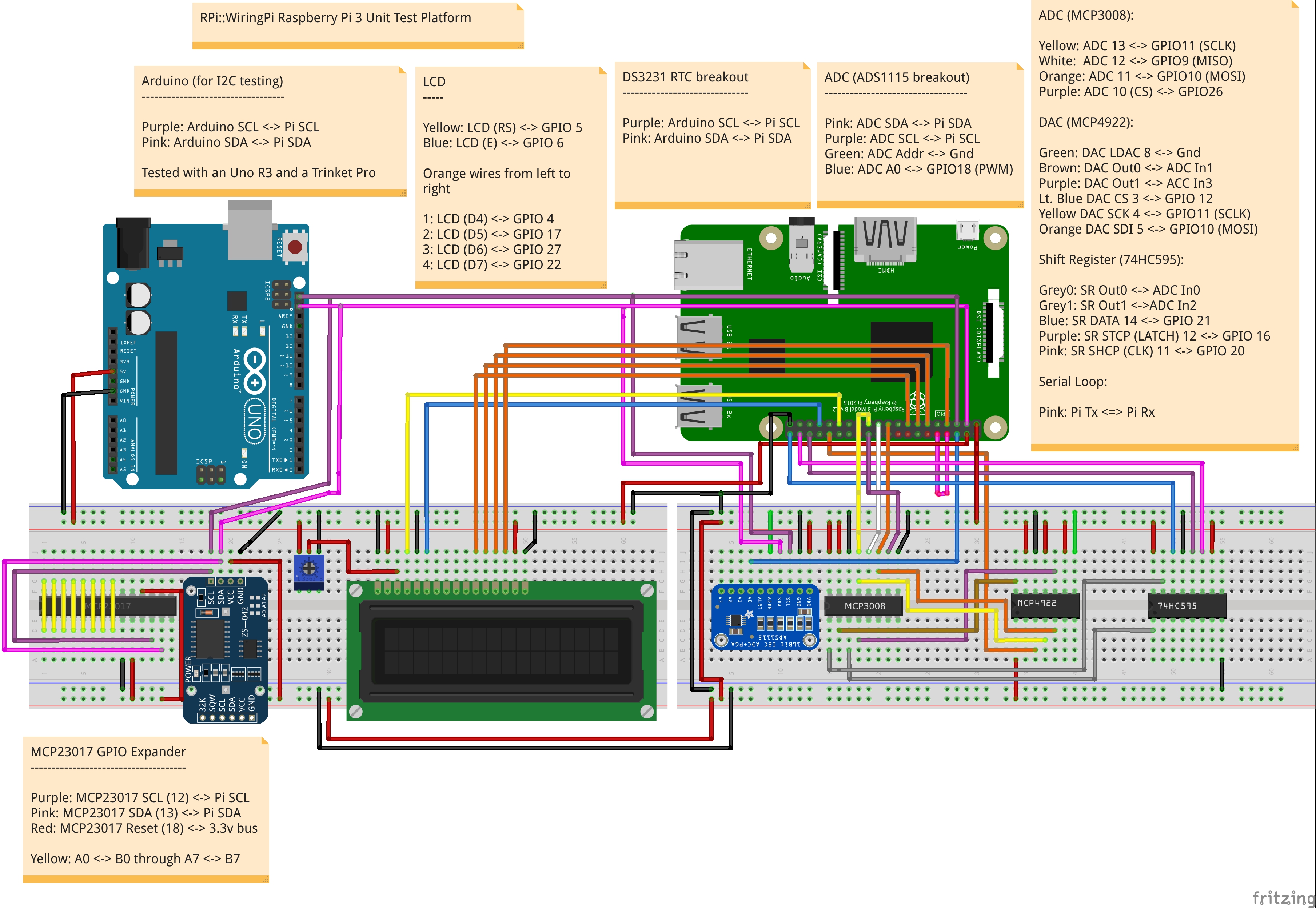
First off, please review the docs/test-platform/README file for the GPIO pins we use for the test physical configuration, and set up the Pi according to the unit test diagram.
Base information
Before running the tests, you need to set a special environment variable so that we know we're on a Pi board. This ensures CPAN testers won't run the tests across all of its platforms:
export RPI_BOARD=1Personally, I set all the environment variables in my /etc/environment file.
There are a couple of test files that require root privileges, but we handle this internally by re-running the file with sudo enabled. This allows all tests but these couple to be run as a standard user.
Author Testing
To run the author tests (manifest, POD etc), set:
export RPI_RELEASE_TESTING=1We use this instead of RELEASE_TESTING, because that typically caused all sorts of grief when installing prerequisites from the CPAN. Other people's distribution's author tests often fail due to having it set.
Multi Object Testing
We've switched over to having shared data between objects and processes. Although it's the default, you still have to enable these tests explicitly by setting the following environment variable:
export RPI_MULTI=1Arduino/I2C
For testing the RPi::I2C module, we have a dedicated Arduino sketch in the docs/sketch directory that we test against. Install the sketch, hook up the I2C between the Pi and the Arduino, and connect a ground pin on the Arduino to the ground bus on the Pi.
The Arudino has a slower I2C bus than the Pi, so we must lower our bus speed. Add the following line to the /boot/firmware/config.txt file (/boot/config.txt on releases before Bookworm), then reboot:
dtparam=i2c_arm_baudrate=10000You then set the following environment variable:
export RPI_ARDUINO=1These tests skip by default.
Serial Port Testing
To test the serial port RPi::Serial library, you must have a loopback between the Tx and Rx pins, and:
export RPI_SERIAL=1These tests will skip by default otherwise.
Note that you must enable serial in raspi-config and disable "terminal over serial", then reboot. On the Pi 3/4 you must also free the header UART from Bluetooth; on the Pi 5 that is unnecessary (Bluetooth has its own UART). Add the appropriate lines to /boot/firmware/config.txt (/boot/config.txt on releases before Bookworm):
enable_uart=1
dtoverlay=disable-bt    # Pi 3 / 4 only; neither needed nor used on the Pi 5
The loopback test talks to /dev/ttyAMA0 (the header UART on the Pi 5, and on the Pi 3/4 once Bluetooth is disabled).
BMP Barometric Pressure Sensor Testing
To test the temperature and barometric pressure from the BMPx80 sensors:
export RPI_BMP=1These tests skip by default.
HCSR04 Ultrasonic Testing
For this test, please see the documentation for RPi::HCSR04, and check the test files for the pins that are needed. After confirmed and connected, set
export RPI_HCSR04=1These tests only occur in automated mode when building on a Perl that doesn't have prerequisites installed.
OLED Display Testing
These tests use the RPi::OLED::SSD1306::128_64 distribution with a 128x64 pixel I2C OLED display. To have these tests execute, set:
export RPI_OLED=1There's a functional script that will display aspects of the system (time, date, temperature and barometric pressure sensor) on an available OLED. While the OLED tests are running, the script automatically disables itself. To operate this functionality:
perl examples/oled_display_date_time_temp.pl &LCD Testing
In order to perform the RPi::LCD test, a 2 row by 16 column or 4 row by 20 column LCD must be connected and operable. Then, set the following environment variable to a true value:
export RPI_LCD=1RTC Testing
To test the RPi::RTC::DS3231 distribution, you must set the following environment variable:
export RPI_RTC=1MCP23017 GPIO Expander Testing
To test the RPi::GPIOExpander::MCP23017 distribution, set the following environment variable:
export RPI_MCP23017=1PWM/SPI Testing
In order to run tests for PWM and SPI, the following environment variable is required to be set:
export RPI_ADC=1Shift Register Testing
To test the shift register functionality, the following environment variables need to be set:
export RPI_SHIFTREG=1
export RPI_MCP3008=1
Digital Potentiometer Testing
Set the following environment variable:
export RPI_DIGIPOT=1We also need the ADS1115 connected and enabled:
export RPI_ADC=1Digital to Analog Converter Testing
To test the functionality of the RPi::DAC::MCP4922, set the following environment variable:
export RPI_MCP4922=1Servo Testing
The servo test (t/325-servo.t) drives a servo on GPIO 18 via hardware PWM and reads its position back through an ADC, sweeping the horn fully left to right and back again. Because it uses PWM, it requires sudo (see RPI_SUDO), and because it reads the ADC, it requires RPI_ADC. Wire the servo and ADC per the test platform, then set all three of the following:
export RPI_SERVO=1
export RPI_ADC=1
export RPI_SUDO=1
These tests skip by default unless RPI_SERVO is set.
Stepper Motor Testing
The test for this uses three photo resistors, with a laser on the stepper. We measure the luminosity to determine if the motor is in each position properly. To run these tests, set the following environment variable:
export RPI_STEPPER=1EEPROM Testing
To test the functionality of the EEPROM code, set the following environment variable:
RPI_EEPROM=1Automated with Test::BrewBuild
Test::BrewBuild has some special features specifically to facilitate the automatic testing of this distribution while on a Raspberry Pi, with provisions that allow you to display the last test run results on an LCD if desired.
WARNING: Note that seemingly from perlbrew 0.86, the output of its exec command doesn't display the perl version if only a single instance of perl is installed. Simply ensure you've got more than one Perl instance installed.
Installing Test::BrewBuild
On the Raspberry Pi, we have to install an SSL development library before the Net::SSLeay dependency can be installed:
sudo apt-get install libssl-devNow you can carry on installing Test::BrewBuild in the normal way:
cpanm Test::BrewBuildFirst, on the Pi you're running, you need to set the RPI_BOARD environment variable to ensure all tests run. I set this to 1 in /etc/environment.
NEXT, install Test::BrewBuild. Then, start the bbtester software in the background:
bbtester start -aThe above bbtester command string will only trigger a test build if the local repository commit checksum differs from the remote. To bypass this check and execute a test run every cycle regardless if the checksums differ or not, send in the --csum|-c flag to bbtester:
bbtester start -a -cNext, run a bbdispatch run against the local tester in --auto mode. The -a flag with no parameters runs continuously, sleeping for a default of 60 seconds between runs. Simply send in an integer value that represents a certain number of runs if desired.
bbdispatch -t localhost -r stevieb9/rpi-wiringpi -aTo use the LCD functionality which displays the last date/time that a test run succeeded, along with the last commit tested and its result (PASS/FAIL), set up an environment variable that contains a comma-separated list of GPIO pin numbers that the LCD is connected to (leave off the last two digits if all you have is a two row by 16 column LCD.
export BB_RPI_LCD=5,6,4,17,27,22,4,20...which represents LCD pins:
RS, E, D4, D5, D6, D7To make it work. I set this one in /etc/environment as well. You then need to restart the dispatcher with the --rpi or the equivalent -R flag:
bbdispatch -t localhost -r stevieb9/rpi-wiringpi -a --rpiThe --rpi flag is rather hidden (but it *is* documented subtly), as this is a feature that most likely I'll be the only consumer of.
Running Continuous Integration At Startup
Simply copy the contents of the t/crontab/crontab.txt file into the pi user's crontab by using the crontab -e command.
Testing Environment Variable List
Here's the contents of my /etc/environment file, setting the various testing environment variables for the full test platform. For LCD, the last two digits (4, 20) are for four row, 20 column units. If you only have a two row by 16 column unit, leave those last two digits off.
RPI_BOARD=1
RPI_RELEASE_TESTING=1
RPI_OBJECT_COUNT=0
RPI_PIN_COUNT=0
RPI_SUDO=1
RPI_ARDUINO=1
RPI_ADC=1
RPI_BMP=1
RPI_EEPROM=1
RPI_MCP3008=1
RPI_DIGIPOT=1
RPI_MCP4922=1
RPI_SHIFTREG=1
RPI_LCD=1
RPI_OLED=1
RPI_SERIAL=1
RPI_HCSR04=0
RPI_STEPPER=1
RPI_SERVO=1
BB_RPI_LCD=5,6,4,17,27,22,4,20
RPI_RTC=1
RPI_MCP23017=1
RPI_MULTI=1
RELEASE_TESTING=0
GMAIL_ADDR=email@addr.com
GMAIL_PW=**********
GMAIL_TO=to@addr.com
GMAIL_SERVER=smtp.gmail.com
RPI_OBJECT_COUNT is the number of valid, existing objects being run across processes before the test suite starts. Auto-startup scripts may have valid registrations for example.
RPI_PIN_COUNT is the number of valid, existing pin objects being used across processes before the test suite starts. Auto-startup scripts may have valid registrations for example.
Both RPI_OBJECT_COUNT and RPI_PIN_COUNT are optional; when unset they default to 0 (the normal case, where nothing else is registered in shared memory). They are not a run gate - RPI_BOARD decides whether the suite runs. Only set them if an auto-startup script genuinely holds registrations before the suite starts; the value must then reflect reality, since the registration tests (eg. t/110-register.t) compare the live object/pin counts in shared memory against these variables. Setting RPI_OBJECT_COUNT=1 when no auto-startup object is actually registered produces got '0', expected '1' style failures - so when in doubt, leave them unset (or 0). Running an individual test by hand needs only:
RPI_BOARD=1 prove -lv t/110-register.tRPI_SUDO enables and disables PWM tests.
RPI_SERVO enables and disables the servo tests. These also require RPI_ADC (to read servo position back) and RPI_SUDO (servos are driven with hardware PWM).
RPI_DIST_RELEASE is not a test gate; set it on a non-Pi machine (eg. a macOS laptop used to cut release tarballs) to bypass the wiringPi/i2c presence checks in the XS distributions' Makefile.PL files so that make dist can run. Leave it unset everywhere else - without it, those checks exit before a Makefile is written, which is what makes CPAN testers without wiringPi report NA instead of FAIL.
I2C Test Platform Connections
The below list shows the I2C addresses in use on the Raspberry Pi in the hardware test platform:
0x04  Arduino Metro Mini
0x05  ATMega-328P IC (not always in I2C mode, so not always available)
0x20  GPIO Expander (one MCP23017; expander test + stepper)
0x3c  OLED (main case)
0x48  ADC ADS 1 (main case)
0x49  ADC ADS 2 (2nd case)
0x57  AT24C32 EEPROM (on same breakout board as RTC)
0x68  DS3231 RTC
0x77  BMP180 Barometric Pressure Sensor
We also have a standalone ATMega328-P chip in use on the test platform. If in I2C mode, it'll show up on the Pi as address 0x05. If we're using it in serial mode, it holds an OLED display at address 0x3c on its own I2C bus, separate from the Pi.
DEVELOPMENT
Section that describes some particulars when developing or adding new external devices to RPi::WiringPi. This section is new, and very incomplete. I'll add things as I think of them.
Pins
Any time you accept a pin number to pass along to an external module for use, you *must* call $pi->register_pin($pin_num) in order to have the cleanup functionality tidy things up properly. Neglecting to do this will prevent the cleanup regimen from knowing about these pins, and therefore will be left in an inconsistent state, possibly causing damage on a different run.
AUTHOR
Steve Bertrand, <steveb@cpan.org>
COPYRIGHT AND LICENSE
Copyright (C) 2016-2026 by Steve Bertrand
This library is free software; you can redistribute it and/or modify it under the same terms as Perl itself, either Perl version 5.18.2 or, at your option, any later version of Perl 5 you may have available.